Site-to-Site VPN
This article explains how to use a Datto Networking Appliance (DNA) to configure site-to-site VPN between multiple network devices.
Environment
- Datto Networking Appliance (DNA)
Description
Site-to-Site VPN allows you to establish a secure connection over the Internet between multiple networking appliances so that your users can better connect to resources across various remote offices.
Prerequisites
- When connecting multiple DNAs to the same network, each DNA must have at least one LAN configured.
- Subnets cannot overlap.
- Site-to-Site VPN allows networking with any device that supports IKEv1 or IKEv2.
- You will need to configure client devices to accept IKEv1 or IKEv2 connections before they will be able to communicate with the Datto Networking Appliance. Contact your device's manufacturer for assistance with this process. Datto is unable to provide configuration assistance for third-party network appliances.
Good to know
-
Datto DNAs do not natively support split-tunneling.
-
When selected, the Dynamic Phase 2 check box in the Phase 2 Site-to-Site VPN options activates Perfect Forward Secrecy (PFS).
-
Dynamic Phase 2 is required on some appliances. Check with your vendor to find if Dynamic Phase 2 is required for a Site-to-Site configuration involving equipment from a non-Datto vendor.
Procedure
IMPORTANT D200s do not support IPSEC-NAT-T and will only permit IPsec traffic with a source port of 500 or 4500.
To access the Site-to-Site VPN card:
1. Log into the DNA web interface, then click Networks.
2. On the Networks page, click the Site-to-Site VPN link. You will see the Site-to-Site VPN card. Here, you can:
- Specify which local subnets are accessible in the IPsec topology.
- Specify which static routes are accessible in the IPsec topology.
- Specify which network objects are accessible in the IPsec topology.
Connecting a DNA
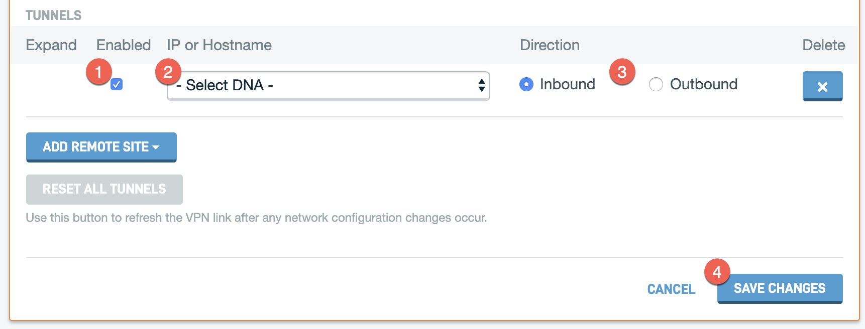
- Check the Enable box.
- In the IP or Hostname box, select the DNA that you wish to add to the network.
- In the Direction column, select the connection type.
- Inbound: Treats the DNA you are configuring as the hub, with the device you are adding to the Site-to-Site VPN card as a client or initiator.
- Outbound: Treats the DNA you are configuring as the client, with the device you are adding to the Site-to-Site VPN card as the server or responder. If this DNA is currently on failover, you must select the Outbound connection.
- Click Save Changes.
Connecting a Non-DNA Device
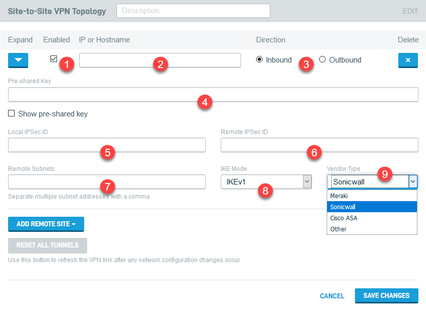
Figure 4: Connecting a non-DNA device
1. Check the Enable box.
2. In the IP or Hostname box, enter the IP address or hostname of the device you wish to add to the network.
3. In the Direction column, select the connection type:
- Inbound: Treats the DNA you are configuring as the hub, with the device you are adding to the Site-to-Site VPN card as a client or initiator.
-
Outbound: Treats the DNA you are configuring as the client/initiator, with the device you are adding to the Site-to-Site VPN card as the server/responder.
4. In the Pre-shared Key field, create a pre-shared key that the DNA will use to communicate securely with the client. Any client you connect to the DNA will also need to communicate with the DNA by using this key.
5. In the Local Ipsec ID field, enter the Ipsec ID you will use on the client to identify the DNA.
6. In the Remote Ipsec ID field, enter the Ipsec ID you will use on the DNA to identify the client.
7. In the Subnets field, enter the segment of the client's network that you want to make available to the VPN.
NOTE When configuring larger networks, ensure that there are no subnet conflicts before saving changes.
8. Select the IKE Mode the client will use to connect (IKEv1 or IKEv2).
9. Select the Vendor Type that matches the IPsec endpoint (router or firewall) to which you are connecting. The following policy and encryption optimizations will be applied to the connection unless you select Other:
Meraki
Strict policy match based on Meraki defaults. MX devices do not support dynamic IP for Site VPN peers.
| parameter | value |
| key mode | IKEv1 |
| phase1 encryption | 3des |
| phase1 integrity hash | sha1 |
| phase1 dh group | group 2 / 1024 bit modulus |
| phase1 lifetime | 28800 sec |
| phase2 encryption | aes128 |
| phase2 integrity hash | sha1 |
| phase2 lifetime | 28800 sec |
Cisco ASA
Strict policy match, based on best settings available on ASA platform.
| parameter | value |
| key mode | IKEv2 recommended |
| phase1 encryption | aes256 |
| phase1 integrity hash | sha1 |
| phase1 dh group | group 5 / 1536 bit modulus |
| phase1 lifetime | 86400 sec |
| phase2 encryption | aes256 |
| phase2 integrity hash | sha1 |
| phase2 lifetime | 28800 sec |
Sonicwall
Based on most compatible Phase 1 policy paired with a secure Phase 2 policy on SonicOS platform.
| parameter | value |
| key mode | IKEv2 recommended |
| phase1 encryption | 3des |
| phase1 integrity hash | sha1 |
| phase1 dh group | group 2 / 1024 bit modulus |
| phase1 lifetime | 86400 sec |
| phase2 encryption | aes256 |
| phase2 integrity hash | sha256 |
| phase2 dh group | group 14 / 2048 bit modulus (enable perfect forward secrecy) |
| phase2 lifetime | 28800 sec |
Other
| parameter | value |
| key mode | IKEv2 default |
| phase1 encryption | AES 128 bit |
| phase1 integrity hash | SHA1 integrity hash |
| phase1 dh group | group 14 / 2048 bit modulus |
| phase1 lifetime | 86400 sec |
| phase2 encryption | aes128 |
| phase2 integrity hash | sha1 |
| phase2 dh group | group 14 / 2048 bit modulus |
| phase2 lifetime | 28800 sec |
If Other is selected, you will have the option to configure IPsec policies and parameters for both Phase 1 and Phase 2. The following options are available:
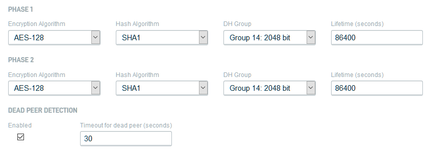
Figure 5: Phase 1 & 2 IPsec policies
Encryption Algorithm: Allows you to specify what encryption algorithm is used. The Triple Data Encryption Standard (3DES), AES-128, AES-192, and AES-256 are available.
Hash Algorithm: Allows you to specify what hash algorithm is used. MD5, SHA1, SHA256, SHA384, and SHA512 are available. AES-XCBC is available exclusively for phase 2.
DH Group: Allows you to specify what Diffie-Hellman exchange (DH group) is used. The following groups and moduli are available:
Regular Groups
Group 1: 768 bit
Group 2: 1024 bit
Group 5: 1536 bit
Group 14: 2048 bit
Group 15: 3072 bit
Group 16: 4096 bit
Group 17: 6144 bit
Group 18: 8192 bit
Prime Order with Prime Subgroups
Group 22: 160 bit
Group 23: 224 bit
Group 24: 256 bit
NIST Elliptic Curve Groups
Group 25: 192 bit
Group 26: 224 bit
Group 19: 256 bit
Group 20: 384 bit
Group 21: 521 bit
Brainpool Elliptic Curve Groups
Group 27: 224 bit
Group 28: 256 bit
Group 29: 384 bit
Group 30: 512 bit
Lifetime (seconds): Allows you to specify, in seconds, how often the IPsec tunnel is renegotiated. The default is 86,400 seconds.
Dead Peer Detection: Enabling this will configure the DNA to detect the existence and validity of the non-DNA peer. You can input, in seconds, the timeout for the dead peer, after which the DNA will terminate the connection to the dead peer.
11. Click Save Changes to save the configuration.
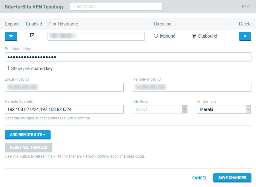
Figure 6: Example of configured DNA and non-DNA clients
Once you save the configuration, your new VPN connections will appear on the Site-to-Site VPN card. The Direction and Role fields indicate the connection type and client role.

Figure 7: Site-to-Site VPN card, overview mode, with configured DNA and non-DNA clients
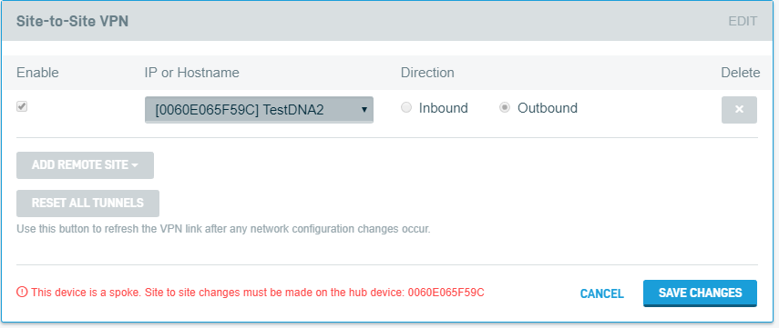
If a DNA is configured as a spoke, it cannot make any changes to the Site-to-Site VPN configuration. To make changes to a spoke, you will need to manage its VPN settings from the device configured as the hub.
Enabling LAN Site-to-Site VPN access
After configuring your Site-to-Site VPN, you specify that it can access any LAN configured on the DNA. Read the DNA: LAN Settings for more information.


